|
|
|
|
Controllable
Electric Reactors Consortium of Russia and the CIS
(CERC) |
|
| About
Cerc Products Articles Contact Home Search | |
 |
MCR 180/500: 3-Phase, 180 Mvar, 500kV
Magnetically Controlled Reactor (Patented)
 |
PURPOSE:
To compensate excess charge power of transmission lines.
To prevent network emergency over-voltage and keep it within 1.0 to 2.5 percent of rated network voltage at point of connection.
To lower by 15 to 20 percent power transmission and distribution losses due to minimization of reactive power transfer through the network.
To reduce by dozens of times the intensity of operating the switching equipment in voltage control circuits.
FIELD OF APPLICATION:
MCRs of this type are used for system and transit grids of 300 to 1150 kV voltage rating.
Connected to busbars of substations or to busbars of 500 kV lines by circuit breaker and disconnector.
COMPLETE EQUIPMENT:
See schematic diagram below.
| Single phase controllable reactor (1) | 3 units |
| Transformer with built-in thyristor converter (2) | 4 units |
| Control, regulation and protection system (3) | 1 unit |
MAIN TECHNICAL DATA:
| Rated power: | 180 MVA |
| Number of phases: | 3 |
| Frequency | 50 or 60 Hz |
| Rated voltage of network winding | 525 kV |
| Rated voltage of control winding | 35 kV |
| Supply voltage of converter | 0.4; 6; 10 kV |
| Supply voltage of control system | 220 V |
| Power change range | 3.6 to 180 MVA |
| Consumed power in forced mode | 360 MVA |
| Voltage setting range | 500 to 525 kV |
| Current setting range | 4 to 198 A |
| No load losses | 150 kW |
| Short circuit losses | 750 kW |
WINDING CONNECTIONS:
Phases of network winding of the MCR reactor are Y-connected and grounded.
The control windings of phases are delta connected.
Transformers with built-in thyristor converters are connected to equipotential points of reactor control windings.
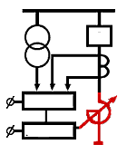
As shown in the schematic below, the control system (3) is connected to the control inputs of transformers with built-in thyristor converters (2), to the current transformers (5) at the controllable reactor phases, and to substation voltage transformers (4) at 500 kV busbars.
OPERATING CONDITIONS:
The 3-phase controllable MCR is designed for outdoor operation in moderate climate conditions at elevations of up to 1000 m above sea level. Each module is placed in an oil-immersion tank with natural cooling. Main parameters of the module are as follows:
| Active materials weight: | 68 T |
| Transport weight: | 120 T |
| Tank dimensions: | 8.2 x 5.9 x 9.4 m |
The associated transformer with built-in thyristor converter is also designed for outdoor operation. It is placed in oil-immersion tank for natural cooling. The main parameters are
| Active materials weight: | 2.1 T |
| Transport weight: | 3.75 T |
| Tank dimensions: | 1.8 x1.15 x 1.95 m |
The control, adjustment, and monitoring system is designed for indoor installation on a substation switchboard panel:
| Weight: | 25 kg |
| Dimensions: | .45 x .25 x .6 m |
PRINCIPLES OF OPERATION:

In the figure above, a measurement system (4, 5) generates a mismatch signal, which triggers a control device (3) that operates a thyristor converter (2). This converter in turn generates direct current, magnetizing the phase magnetic system and producing a smooth change in reactive power consumed by the phases of reactor (1). Automatic stabilization of the voltage occurs at the point of reactor connection. With increase in voltage deviation to 2.5% of the specified setting, the power consumed in reactor (1) varies smoothly from 36 kVA to 180 MVA (from idling to rated power) in proportion to the mismatch signal, with an equivalent time constant that does not exceed 1 seconds.
Compensation of excess charge power of transmission lines is caried out automatically by means of an operator-preset fixed value for the angle adjustment of converter (2). In this case the MCR's idle current can be preset from 4 to 198 A.
Upon occurance of switch or alarm overvoltage at the point of connection or in the transmission line, 35 kV circuit breaker of short-circuit winding (7) is put into operation. As a result, not depending on the operating mode of converter (2) and control system (3), the power of the reactor increases in an inertia-free manner, to as much as twice the rated value 360 MVA. Allowed time of forced mode is up to 30 seconds.
EFFICIENCY OF APPLICATION:
The design, weight, dimension, and maintenance parameters of the MCR-180/500 are similar to those of general-purpose, double-winding transformers of the same power and voltage class. This provides excellent device effectiveness and reliability.
MCR-180/500 operation does not require specific training of maintenance personnel.
Time of recovery of outlay for MCR-180/500 is 1.5 to two years.
TOTAL COST OF OWNERSHIP (TCO)
As a percentage of ex-works price TCO is as follows:
| Delivery (brokerage, customs, etc.) | 5 to 10% |
| Construction and installation | Average 25% (depending on location) |
| Operation and maintenance | 4% per annum |
In other words, the TCO of an MCR is similar to that of a transformer of the same class.
MEAN TIME BETWEEN FAILURE (MTBF)
CERC guarantees its MCR's for a lifetime of not less than 25 years, with first major maintenance guaranteed not to occur within 12 years.
Each phase of the reactor, its grounding filter and current-distortion corrector (an LC filter) are guaranteed for a minimum of 3 years.
The power control system, including the transformer with its built-in thyristor subsystem is guaranteed for one year. The average practical time to failure of smaller MCR's is 5 years.
 |
